![]()
![]()
![]()
Next: Lab 4
Up: EEE 407/591 - Digital Previous: Lab 2
Lab
3 - Linear Phase, FIR Filter Design by Windowing and IIR Filters
Objectives
FIR filters with linear phase comprise an important
class of LTI sytems. This exercise examines the four types of symmetric impulse
responses that will result in linear phase. In addition, constraints on the
zeros of linear phase filters will be studied and the group delays will be
computed. Knowledge of linear phase systems will then be applied to design FIR,
linear phase filters by windowing using both parametric and non-parametric
windows.
Filter design by windowing involves first
calculating the impulse response for an ideal filter. Since the ideal impulse
response will not be time-limited, it must be truncated at some point in order
to implement it in a practical system. The truncation is done using both
non-parametric and parametric windows. Non-parametric windows have a fixed
shape and include rectangular,
We will also study FIR filter design by
frequency sampling method and Parks-McClellan method. The frequency sampling method allow us
to design FIR filters for both typical frequency selective filters (low-pass, high-pass, band-stop and band-pass filters)
and filters with arbitrary frequency response. The resulting filter will have a
frequency response that is exactly the same as the original response at the
sampling instants. However, between the sample points the response will
generally be different. To obtain a good approximation to the desired frequency
response we must take a sufficient number of frequency samples.
Parks McClellan algorithm is the most widely
used algorithm for designing the optimal linear-phase FIR filters. The design
is based on the minimization of the peak absolute value (maximum) of the
weighted error. The minimized weighted error function exhibits an equi-ripple
behavior.
Finally, a filter will be designed using 4
different IIR methods and the results will be compared.
Introduction
The following 4 blocks from J-DSP will be
useful in performing this exercise.
![]() The Window Block. J-DSP
contains a Window block under the basic blocks menu. This block will be
useful in the second and third problems to truncate the ideal impulse response.
This block takes an input signal and multiplies it with a window of specified
length and type. In the case of the Kaiser window, the
The Window Block. J-DSP
contains a Window block under the basic blocks menu. This block will be
useful in the second and third problems to truncate the ideal impulse response.
This block takes an input signal and multiplies it with a window of specified
length and type. In the case of the Kaiser window, the ![]() parameter must also be entered. After changing any of the settings
in the window block, press the update block for the changes to
take effect.
parameter must also be entered. After changing any of the settings
in the window block, press the update block for the changes to
take effect.
The filter blocks menu in J-DSP
also contains a Kaiser block and a FIR block. These blocks will
produce filter coefficients based on the window design method used in problems
2 and 3, however, they will only give up to 10th order filters. Since the
filters in problems 2 and 3 are of orders larger than 10, use the Window
block instead.
![]() The Freq. Sampling Block
under filter blocks.
The Freq. Sampling Block
under filter blocks.
![]() The Kaiser Design Block under
filter blocks.
The Kaiser Design Block under
filter blocks.
![]() The IIR block. The IIR
block is also found uder the filter menu and is used for designing IIR filters.
To design an IIR filter, specify one of four IIR design methods (Butterworth,
Chebychev I, Chebychev II or Elliptic), the filter type(high-pass, low-pass,
etc.), the cutoff frequencies and the tolerances. The cutoff frequencies should
be entered as percentages of pi. For example, a cutoff frequency of 0.5pi
should be entered as 0.5. The IIR block can be connected to a PZ-plot
block to see a plot of the filter's poles and zeros and to a Freq-Resp
block to see its frequency response. It can also be connected to the bottom of
a filter block which will set the filter coefficients of that block to
the coefficients produced by the IIR filter design block.
The IIR block. The IIR
block is also found uder the filter menu and is used for designing IIR filters.
To design an IIR filter, specify one of four IIR design methods (Butterworth,
Chebychev I, Chebychev II or Elliptic), the filter type(high-pass, low-pass,
etc.), the cutoff frequencies and the tolerances. The cutoff frequencies should
be entered as percentages of pi. For example, a cutoff frequency of 0.5pi
should be entered as 0.5. The IIR block can be connected to a PZ-plot
block to see a plot of the filter's poles and zeros and to a Freq-Resp
block to see its frequency response. It can also be connected to the bottom of
a filter block which will set the filter coefficients of that block to
the coefficients produced by the IIR filter design block.
J-DSP
For this lab, use the J-DSP program. Click
the link below
Problems
![]() Problem
1: FIR linear phase systems
Problem
1: FIR linear phase systems
Consider the following four impulse
responses.
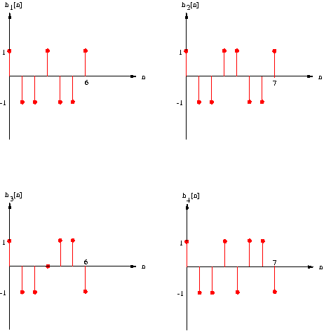
- (a) Find the transfer function for each of
the above impulse responses and implement each system as a filter
block in J-DSP. Plot the frequency response (magnitude and phase) of each
system using linear scaling. Save the graphs of the H1(jw),
H2(jw), H3(jw), H4(jw) as graph1,
graph2, graph3 and graph4 respectively.
- (b) Derive from the symmetry condition in the
time domain (in terms of h[n]), the symmetry condition in the Z-domain (in
terms of H(z)).
- (c) For each system, describe the symmetries
of the zeros of H(z) (use J-DSP's PZ-Plot block to find the roots).
- (d) Determine the group delay of each system.
Apply a delta at the input of the filter, then take the FFT of the output.
Connect the FFT block to a plot block and use the tabulated
values in the plot dialog box to derive the exact group delay.(Hint: When
calculating the group delay, make sure both vertical and horizontal axis
have the same units.)
![]() Problem
2: FIR Filter Design by Windowing
Problem
2: FIR Filter Design by Windowing
Let
![]()
be the ideal impulse response of a
low-pass filter. Design a FIR filter with generalized linear phase by
truncating this ideal impulse to 60 samples.
For all parts of this problem, use a signal
generator block with the following settings:
- Signal type: Sinc
- Gain: 0.2
- Pulsewidth: 120
- Periodic: No
- Time Shift: 30
These
settings provide a shifted, causal version of the impulse response. Use a window
block to truncate the ideal impulse response using each of the following window
types.
- (a) Rectangular
- (b) Triangular (
- (c) Hamming
- (i) Include a diagram of your system in part
(a). Save diagram as graph5
- (ii) Plot the frequency response of the
filter on a dB scale for part (a) and save the plot as graph6.
- (iii) Plot the frequency response of the
filter on a dB scale for part (b) and save the plot as graph7.
- (iv) Plot the frequency response of the
filter on a dB scale for part (c) and save it as graph8.
- (v) Notice the differences in main lobe
width, side lobe height and slope in the transition region of the
magnitude response.
![]() Problem 3: Filter design using the Kaiser
window method
Problem 3: Filter design using the Kaiser
window method
Design a high-pass filter with generalized
linear phase using the Kaiser window method.
Use the following specifications:
![]()
- (a) Find the minimum length M of the impulse
response where M is even. Compute the value of the Kaiser window parameter
 for a filter that meets the
specifications above.
for a filter that meets the
specifications above. - (b) Determine analytically the ideal impulse
response.
- (c) Use J-Dsp and the Kaiser window
determined above to plot the frequency response of the filter on a dB
scale and save the plot as graph9. Make sure that your
filter has a generalized linear phase.
- (d) Find the group delay of the filter.
Hints:
To implement this filter, you need two signal generator boxes, an Adder box, a
window box,a junction box , FFT box and 2 plot boxes. Subtraction can be done
by assigning a negative amplitude to one signal.
Problem 4: Filter design using the frequency sampling
block
Step 1:
- Line segments = 1.
- N (samples) = 16. (Filter order = 15)
Next we draw the desired (ideal)
frequency response that will be sampled at equal intervals. To construct a line
segment the user has to place two points by clicking on the desired
positions. For a low-pass filter design it is recommended to place the first
point on the top left corner with amplitude one and the second point close to
the 0.25*pi position (cut-off frequency) with amplitude one.
- Place 2nd point à at 0.25*pi with
amplitude one
Press Update
to pass the coefficients to the filter. If during the drawing procedure the
user wants to correct or start over again, simply press Reset and follow again
the instructions above.
Save the following graphs.
- The drawn frequency response
(FreqSamp block) (graph11)
Step 2:
We can improve the
amplitude response (decreased sidelobe level) of the frequency sampling filter
by introducing a wider transition band between the passband and stopband of the
drawn (ideal) frequency response.
- N (samples) = 16.
For two line segments the
available points to design the desired frequency response are three (3). Place
the first point as before (Step 1) and instead of placing the second point at
0.25*pi, place it at 0.2*pi. Finally, put the third point at
0.35*pi with amplitude zero.
- Place 2nd point à at 0.2*pi with
amplitude one (fourth vertical line)
- Place 3rd point à at 0.35*pi with
amplitude zero (seventh vertical line)
Press Update
to pass the coefficients to the filter. Observe the frequency response of the designed
filter at the output of the FFT block and measure the highest sidelobe
level (in dB). Measure also the
amplitude level (in dB) at the cut-off frequency 0.25*pi (The cut-off frequency
didn’t change due to the wider transition band).
Save the following graphs.
- The frequency response of
the filters (at the output of the FFT block) (graph12)
- The drawn frequency response
(FreqSamp block) (graph13)
![]() Problem 5: Filter design using the Parks-McClellan algorithm
Problem 5: Filter design using the Parks-McClellan algorithm
Using the Parks-McClellan (PMC) algorithm, design
filters with the following specifications.
Filter – 1
specifications
- Type – low-pass filter
- Cut-off frequencies:
- Passband (PB) cut-off frequency: Wp1 = 0.1 * pi
- Stopband (SB) cut-off frequency: Ws1 = 0.3 * pi
- Tolerances: PB = 3 dB; SB
= 20 dB
Design a low-pass filter for the above
specifications, and respond to the following:
- Save the frequency response in dB as graph15
- What
is the order of the filter?
- Design
the FIR filter using the kaiser window method for the above
specifications, and find the order of the filter. Compare your results against the PMC method.
Filter - 2 specifications
- Type – high-pass filter
- Cut-off
frequencies:
- Passband
(PB) cut-off frequency: Wp1 = 0.9
* pi;
- Stopband
(SB) cut-off frequency: Ws1 = 0.7
* pi
- Tolerances:PB = 5 dB; SB = 20 dB.
Design a high-pass filter for the above
specifications,
- What
is the order of the filter?
- Design
the FIR filter using the kaiser window method for the above
specifications, and find the order of the filter. Compare your results
against the PMC method.
Problem 6: Filter design comparison using Parks-McClellan, Kaiser
and Frequency sampling method
- Type:
low-pass filter
- Cut-off
frequencies: Passband (Wp) cutoff frequency: Wp1 = 0.2 * pi.
Stopband (Ws) cutoff frequency: Ws1 = 0.36* pi
- Tolerances: PB = 10 dB; SB
= 20 dB
B. Kaiser (select Kaiser FIR
Filter Design block)
- Type:
low-pass filter
- Cut-off
frequencies: Passband (Wp) cutoff frequency: Wp1 = 0.15 * pi.
Stopband (Ws) cutoff frequency: Ws1 = 0.35* pi
- Tolerances: PB = 10 dB; SB
= 29 dB
C. Frequency sampling
***Same set up as problem 4, step 2.
Observe the frequency response
of the designed filters at the output of the FFT block and measure the
highest sidelobe level (in dB) for
each filter design. Measure also the amplitude level (in dB) at the cut-off
frequency 0.25*pi.
Save the following
graphs.
- The frequency response of
the Kaiser Window filter (at the output of the FFT block) (graph16)
- The frequency response of
the Parks-McClellan filter(at the output of the FFT block) (graph17)
- The frequency response of
the frequency sampling filter(at the output of the FFT block) (graph18)
![]() Problem
7: IIR Filter Design
Problem
7: IIR Filter Design
In this exercise, you will design an IIR
filter with JDSP. The filter will be designed using four different IIR methods
(Butterworth, Chebychev I, Chebychev II and Elliptic) so that results of the 4
different methods can be compared. The spefications for the filter are shown
below.
- Type=Lowpass
- Passband cutoff frequency: wp1=0.4pi
- Stopband cutoff frequency: ws1=0.6pi
- Tolerance in passband=1.0dB
- Tolerance is stopband= -45.0dB
Use J-DSP's IIR block to design the
filter using each one of the four IIR methods mentioned above. You may want to
create all 4 of the filters simultaneously with J-DSP so you can compare the
frequency response and pole-zero plot of each one. To determine whether the
filter is monotonic or equiripple in the stopband, view the frequency response
on a dB scale. To determine whether the filter is monotonic or equiripple in
the passband, view the frequency response on a linear scale. As you compare the four design methods, answer the following
questions.
- Which filter requires the highest order to
meet the specifications?
- Which filter requires the lowest order to
meet the specifications?
- Which IIR design methods produce a stable
filter?
- Do any of the four filters have linear phase?
- Which of the four filters is equiripple in
the passband and monotonic in the stopband?
- Which of the four filters is monotonic in the
passband and equiripple in the stopband?
- Which of the four filters is equiripple in
both the stopband and the passband?
- Which of the four filters is monotonic in both
the stopband and the passband?
- For the filters which are monotonic in the
passband, where are all the zeros located?
![]()
![]()
![]()
Next: Lab 4 Up: EEE 407/591 -
Digital Previous: Lab 1
Copyright 2008
Andreas Spanias, MIDL,